No products


M328 Multi Component LCR Tester with Graphical Interface
0104110000019424
New product
Multi M328 Graphics Interface Tester is ideal to find out what features have certain electronic components, such as transistors, diodes, resistors, etc.
See Description for more details about the product.
Add to cart now!
10 Items
- Write a review
More info
Overview
Multi M328 Graphics Interface Tester is ideal to find out what features have certain electronic components, such as transistors, diodes, resistors, etc.
Specifications
• Supply voltage: 9 V
• Measures the characteristics of the following parts:
- NPN / PNP transistors
- MOSFET / JFET N / P transistors: gate threshold, gate capacitance
- Diode
- Thyristor
- Capacitors: 25 pF - 100 mF and ESR for maximum 2 uF
- Coil: Inductance between 0.01 mH - 20 H
- Resistors: maximum resistance 50 M Ω
Features
- Newly added power-on voltage detection function
- Automatically detect NPN and PNP transistors, N-channel and P-channel MOSFETs, diodes (including double diodes), thyristors, transistors, resistors and capacitors, etc.
- Automatically test the component pins and display them on the liquid crystal
- Can detect the amplification factor and base of transistors, MOSFET protection diodes, etc. to determine the forward bias voltage of the emitter transistor
- Measure the gate threshold voltage and gate capacitance of the MOSFET
- The display uses 12864 lcd liquid crystal (128 * 64 characters)
- Higher test speed, valid period Component test: within 2 seconds (except for larger capacitors, the measurement of large capacitance also takes a long time, the measurement time is 1 Minutes is normal)
- One-key operation, power-on test, one-key operation.
- Power consumption shutdown mode: The automatic shutdown function of less than 20 nA can avoid unnecessary waste, save battery energy, and improve battery life.
Instructions for Use
1.Connect the module to a 9 V battery;
2.Connect the component to be analyzed.
The ZIF's bottom-left foot has 3 distinct points (numbered on the back with "1", "2" or "3"). Lift the lever to insert a component into the socket, and then let it down to fix the component. To analyze a piece, you must enter the component in differently numbered points.
The module does not take into account the polarity, so it does not matter how you connect the components because the multi-tester automatically detects this.
3.Power the multi-tester.
Once you have assured that you have mounted the correct piece, press the bottom right button to start the multi-tester. Now it automatically detects the inserted component and displays the specific information. In case you installed the wrong track or is broken, the following error will appear on the screen: "No, unknown or damaged part".
5. Set the contrast.
The contrast of the screen can be changed using the main button. Without plugging any components into the socket, hold down the button until "Contrast" appears on the screen. Now you have to press the button repeatedly until you reach the desired contrast.
6. Auto-calibration.
The module has auto-calibration function. To activate, you must connect all the distinguished pin (1, 2, 3) with very low resistance. Now you need to follow the instructions on the LCD, such as inserting a capacitor between pins 1 and 3. At the end of the test, your device is calibrated.
Don't delay, buy today.
Add to cart now!
Reviews
Customers who bought this product also bought:
-
ESD-15...
These ESD-15 anti-static curved tweezers are...
₱50.00
-
HC-SR501 PIR...
The HC-SR501 Pyroelectric Infrared Sensor is...
₱74.00
-
Plusivo...
Premium Assorted Resistors: It includes the...
₱139.00
-
NE555 Timer...
The NE555 timer is a user-friendly integrated...
₱15.00
-
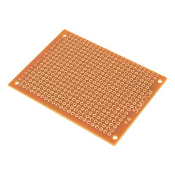
Prototyping...
This is a 50 x 70 mm universal PCB, suitable to...
₱9.00
-
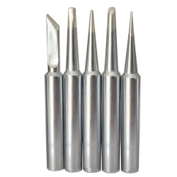
Soldering...
5 pcs Set Soldering Iron Tips See description...
₱59.00
-
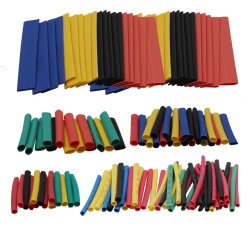
200 pcs...
Heat shrink tubing has been designed to offer...
₱199.00
-
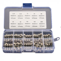
5x20 mm Fuse...
The product supports a maximum voltage of 250...
₱174.00
-
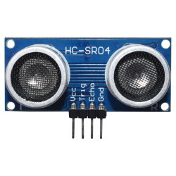
HC-SR04...
The HC-SR04 ultrasonic sensor is one of the...
₱44.00
-
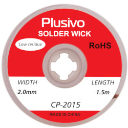
2 mm...
This is 2mm Desoldering Wick (1.5 m) CP-2015...
₱34.00