No products


12 V Relay with Adjustable Delay
0104110000023674
New product
Regular normal relay mode with delay.
See Description for more details about the product.
Add to cart now!
1 Item
Warning: Last items in stock!
- Write a review
More info
Technical Specifications
- Supply voltage: 12 V DC;
- Supported maximum voltage: 250 V AC or 30 V DC;
- Maximum supported current: 10 A;
- Dimensions: 5.5 cm x 2.9 cm x 1.8 cm.
Instructions for Use
1. Powering the module.
The module is powered by a 12 V DC voltage. Screw terminals are marked with VCC and GND.
WARNING! Be careful to observe the polarity, thus risking damage to the product.
2. Relay coupling.
The relay is coupled when the connection between the red-pinned pins is attached to the picture attached below and a configurable time is activated with the S1, S2 and S4 jumper and via the blue potentiometer marked TIME-ADJ. The green LED illuminates during the relay activation.
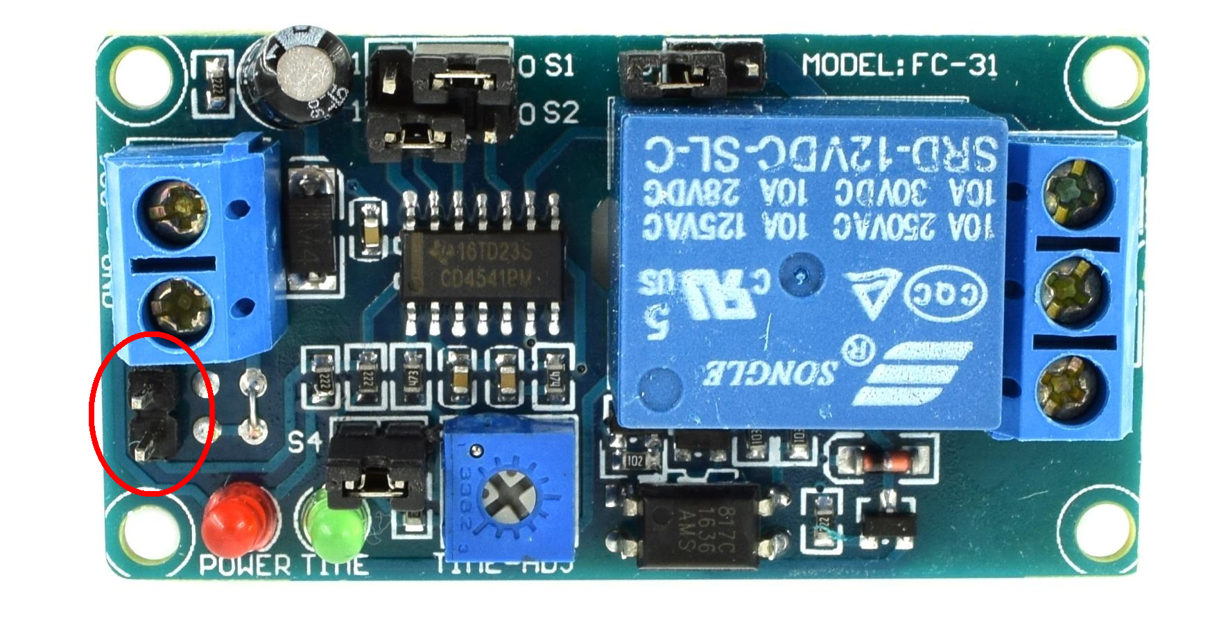
3. Setting the coupling time.
Refer to the attached table below to configure the relay switching time. Also, the relay is switched on when the green LED is on.
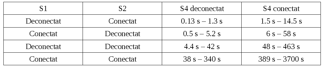
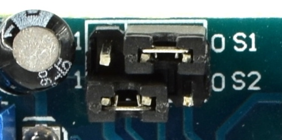
Example: In the attached picture below, jumper S1 is disconnected and jumper S2 is connected. Thus, the coupling time is between 0.13 seconds and 1.3 seconds. Then the time is adjusted with the blue potentiometer. The time decreases when it is rotated counterclockwise and increases when it is rotated clockwise.
Don't delay, buy today.
Add to cart now!
Reviews
Customers who bought this product also bought:
-
LM2596 DC-DC...
This is an LM2596 DC-DC module with voltage...
₱119.00
-
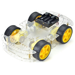
Robot...
This is a very simple and easy to install 4...
₱840.00
-
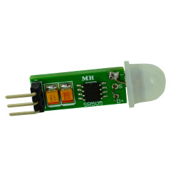
HC-SR505...
This HC-SR505 is a passive infrared motion...
₱44.00
-
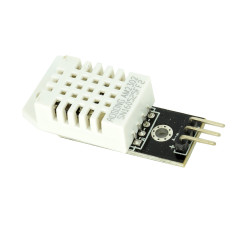
DHT22...
DHT22 is a small, handy, and inexpensive...
₱139.00
-

Ground...
This soil moisture sensor is used to read the...
₱59.00
-
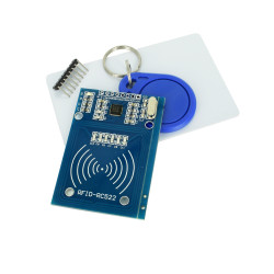
MFRC522 RFID...
This RFID reader module is based on the MFRC522...
₱118.00
-
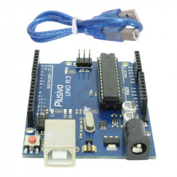
UNO R3...
The Arduino open source platform is based on...
₱329.00
-
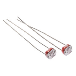
Photoresisto...
This product is light-sensitive and very useful...
₱6.00
-
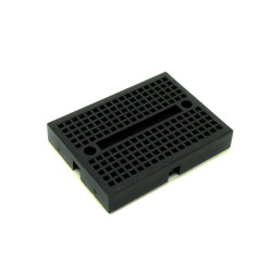
SYB-170...
This black mini breadboard is ideal for your...
₱22.00
-
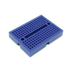
SYB-170...
This blue mini breadboard is ideal for your...
₱22.00