No products
")
")
")
")
12 V Relay Module with Adjustable Delay (220 V)
0104110000020574
New product
The 12 V adjustable delay relay is useful in projects where you need to control 230 V AC consumers.
See Description for more details about the product.
Add to cart now!
2 Items
Warning: Last items in stock!
- Write a review
More info
Overview
This product is a 12v delay module module with a new digital LED countdown display. Using high-quality genuine Songle power relay military-grade double-sided PCB material, stable performance can be widely used in various control switch places. The product delay time can be set by itself, and can be set by pressing the button. After the setting is set, it will count down according to the set value after the next power-on start (power-down memory function). The product is accurate time delay, the error is 0.01% per second, the delay is 0-999 seconds, and the LED changes every 1 second. LED digital display normally open trigger delay 12V relay module, which can be triggered by an external signal. When the power is turned on, the power LED light is on, but the relay does not work. When there is an external trigger (high power or high level trigger) (such as the button is connected to the positive pole of the power supply instantly), the relay starts to work, the countdown delays, when the delay time expires, After that, the relay is disconnected. The module is triggered at high level, and the counting time is 0-999 seconds.
This product has a wide range of applications and can be used in many fields. The product has a working low power consumption mode, long press the left button to turn off the digital tube display or start to display. The input and output of the product are equipped with optocoupler isolation to enhance anti-interference ability and ensure stability.
Specifications
- Voltage: Voltage 12V
- Size: 63.6mm × 33.1mm
- Current: about 12ma in standby, about 50ma when the relay is working
- Load: 250V 10A below AC or 30V below 10A DC
Operating mode:
When the power is turned on, the relay does not work. The trigger terminal is triggered by a button or PNP sensor. When there is a high level trigger (or the button is connected to the positive pole of the power supply instantly), the relay starts to work, and the countdown delays. When the delay time expires, the relay disconnect. It can be described more generally like this: the signal is triggered, the device starts to work, and when the time is up, the device stops working.
Instructions for Use
1. Connect the consumer to the relay.
>There are several ways to connect a consumer (or more consumers) to the relay. The simplest and most common way is to interrupt a thread (phase or null) and connect it to the middle pin ("COM" - Common) and one of the other two pins ("CB" is equivalent to NC- Normally Closed or "CK" is equivalent to NO - Normally Open).
If it connects to the CK pin, the circuit closes when the timer is activated. When connected to CB, the circuit remains closed until the timer is activated.
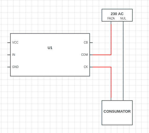
CAREFUL!!! It is recommended to disconnect the consumer from the 230 V AC network until you reach step 5 to avoid possible accidents.
2.Enter the module with a 12 V DC source.
Mode feeding is done through the screw terminals.
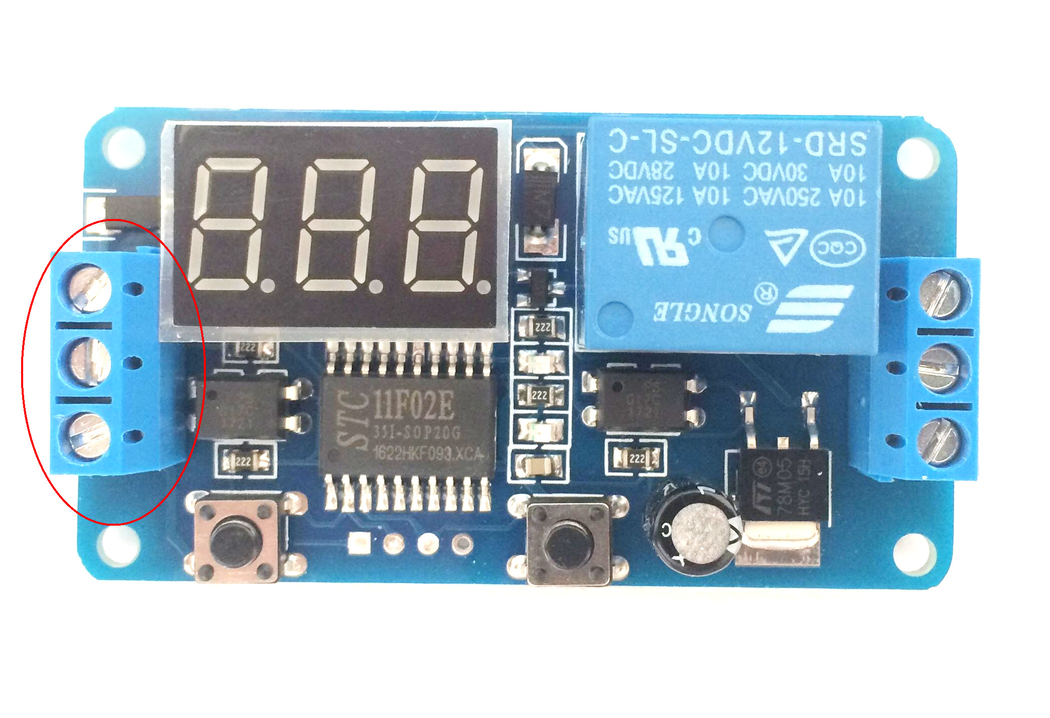
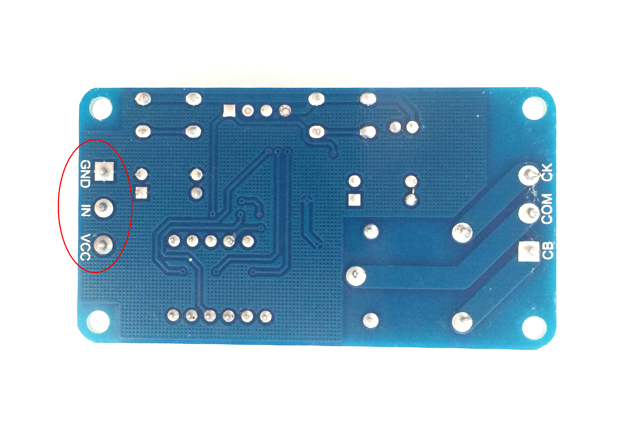
The corresponding GND and VCC pins are marked on the back. Be careful not to reverse polarity to risk spoiling the product.
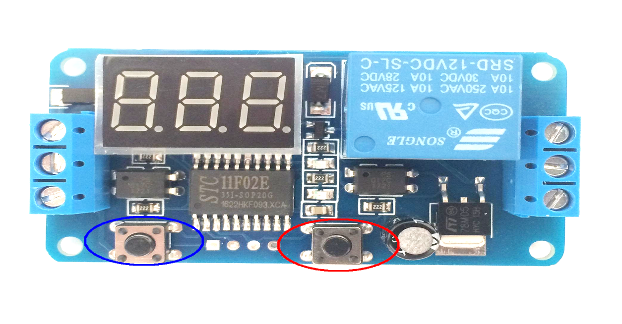
3. Configure the relay activation delay.
Configuration is done using the two buttons mounted on the board.
To set the activation time, proceed as follows:
- The rounded blue button has the role of selecting the next digit from left to right.
- The red encircled button has the role to increment with the 1 digit selected.
4. Connect the trigger to the IN pin.
To activate the relay, it is necessary to apply a voltage of 5 V to 12 V on the IN pin. This can be done using an Arduino or any other voltage source. If two sources are used (for example one for power supply and one for Arduino), do not forget to connect the GND pin of the Arduino board to the module's GND pin.
The number displayed on the segment screen is the number of seconds while the relay is on.
The on-screen number indicates the number of seconds that the relay has to switch on as soon as a voltage is detected on the IN pin (located between GND and VCC).
5. Feed the consumer from the 230 V network.
Once you've finished setting up the delay and making the necessary connections, you need to make sure that they are done properly. You can now connect the consumer to the AC network. Now all you have to do is apply a voltage to the IN pin to activate the relay.
Don't delay, buy today.
Add to cart now!
Reviews
Customers who bought this product also bought:
-
5V Active...
This buzzer can be connected to the standard...
₱18.00
-
5 A PWM...
This 5 A PWM driver module with reverse...
₱59.00
-
Stepper...
This product contains a 5 V stepper motor and a...
₱84.00
-
2 Wire DC...
This 2-wire DC voltmeter panel is a highly...
₱49.00
-
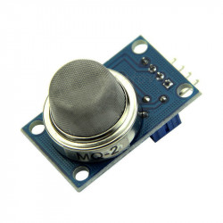
MQ-2 Gas...
This MQ-2 gas sensor module is used for gas...
₱139.00
-
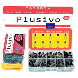
Plusivo BJT...
BJT Transistor Assortment Kit: It includes the...
₱179.00
-
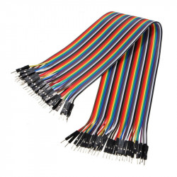
30 cm 40p...
Ideal wires for making connections between...
₱129.00
-
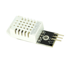
DHT22...
DHT22 is a small, handy, and inexpensive...
₱139.00
-
DC 3-24V...
Piezoelectric active buzzer 3V-24V DC3-24V...
₱89.00
-
SG90 Micro...
This mini servo motor is designed for radio...
₱79.00